 +86-13925515590
 kleinma@aliyun.com


Custom Cover Glass Design: Dimensions, Tolerances and Cutouts

Custom Cover Glass Design: Dimensions, Tolerances and Cutouts
Designing custom cover glass involves more than selecting a glass thickness and specifying an outside dimension. For OEM display manufacturers, the geometry of the glass must work with the housing, display module, touch sensor, mounting structure and decorative printing.
A panel can meet its nominal dimensions and still cause assembly problems if a hole is slightly misplaced, a corner radius is unsuitable or the printed border covers part of the active display area.
These details should be considered before production begins. A well-prepared drawing helps the glass manufacturer evaluate machining feasibility, identify potential risks and avoid unnecessary sample revisions.
This guide explains the main design considerations for custom cover glass, from dimensional tolerances and CNC cutouts to edge finishing and black silk-screen printing.
1. Why Custom Cover Glass Design Matters
In electronic equipment, cover glass is often one of the first components that connects the product’s external appearance with its internal mechanical structure.
Depending on the application, it may need to:
- Protect an LCD or touchscreen display.
- Provide a defined viewing area.
- Accommodate camera lenses, sensors and indicator lights.
- Fit precisely into a plastic or metal enclosure.
- Support adhesive bonding or optical lamination.
- Maintain a consistent decorative appearance across production batches.
For example, an industrial HMI panel may require several openings for buttons, indicator lights and mounting components. A consumer electronic display may instead require a narrow black border, rounded corners and a precisely positioned visible area.
These applications have different engineering requirements. A drawing should therefore describe the actual assembly conditions rather than simply provide the overall length and width.
For OEM projects, the design review should take place before tooling, sample production or mass manufacturing.
2. Selecting Glass Dimensions and Thickness
The first step is defining the overall dimensions and nominal thickness of the glass.
The outside dimensions determine whether the component fits its housing, while thickness influences the mechanical structure, weight, processing route and bonding arrangement.
Common design considerations include:
Overall dimensions
Specify the finished length and width, including any rounded or irregular corners. For non-rectangular panels, provide enough dimensions to define the complete external profile.
Glass thickness
The selected thickness should be evaluated against the application, panel size, support conditions and strengthening requirements. Do not select thickness based on appearance alone.
Corner geometry
Rounded corners are common in touchscreen panels and consumer electronics. Specify the radius of each corner rather than relying on an approximate visual drawing.
Assembly clearance
Consider the space between the glass and its surrounding frame. The finished component must account for the dimensional variation of both the glass and the mating parts.
A useful design practice is to distinguish the nominal glass dimensions from the dimensions that directly affect assembly.
3. Understanding Custom Cover Glass Tolerances
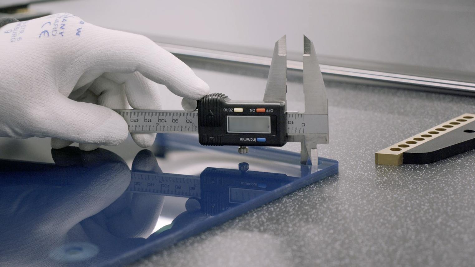
Dimensional tolerance is one of the most important subjects to discuss with a glass manufacturer.
A drawing may specify a nominal dimension of 150 mm, but the manufacturer also needs to know the acceptable deviation from that dimension.
For example, a drawing might specify:
- Nominal width: 150 mm
- Nominal height: 100 mm
- Thickness: 2.0 mm
- Width tolerance: ±0.2 mm
- Height tolerance: ±0.2 mm
These are illustrative design values, not universal manufacturing capabilities or recommended tolerances for every application.
The appropriate tolerance depends on the glass material, thickness, panel geometry, machining method, edge finishing and production process.
Three areas deserve particular attention.
Overall dimensional tolerance
This controls the finished external size of the glass. It becomes especially important when the component fits inside a closely dimensioned frame.
Hole and cutout positioning tolerance
The location of an opening may be more important than its diameter. Even a correctly machined hole can cause assembly problems if its center is positioned incorrectly.
Thickness tolerance
Thickness variation may affect adhesive gaps, mechanical mounting, optical bonding and the height of the finished assembly.
Avoid specifying extremely tight tolerances for every dimension without a functional reason. Tighter requirements can increase manufacturing difficulty, inspection requirements and production cost.
For general background on dimensional tolerance systems, refer to ISO 286-1: Geometrical Product Specifications. This standard covers linear size tolerance systems; it is not a glass-specific manufacturing acceptance standard.
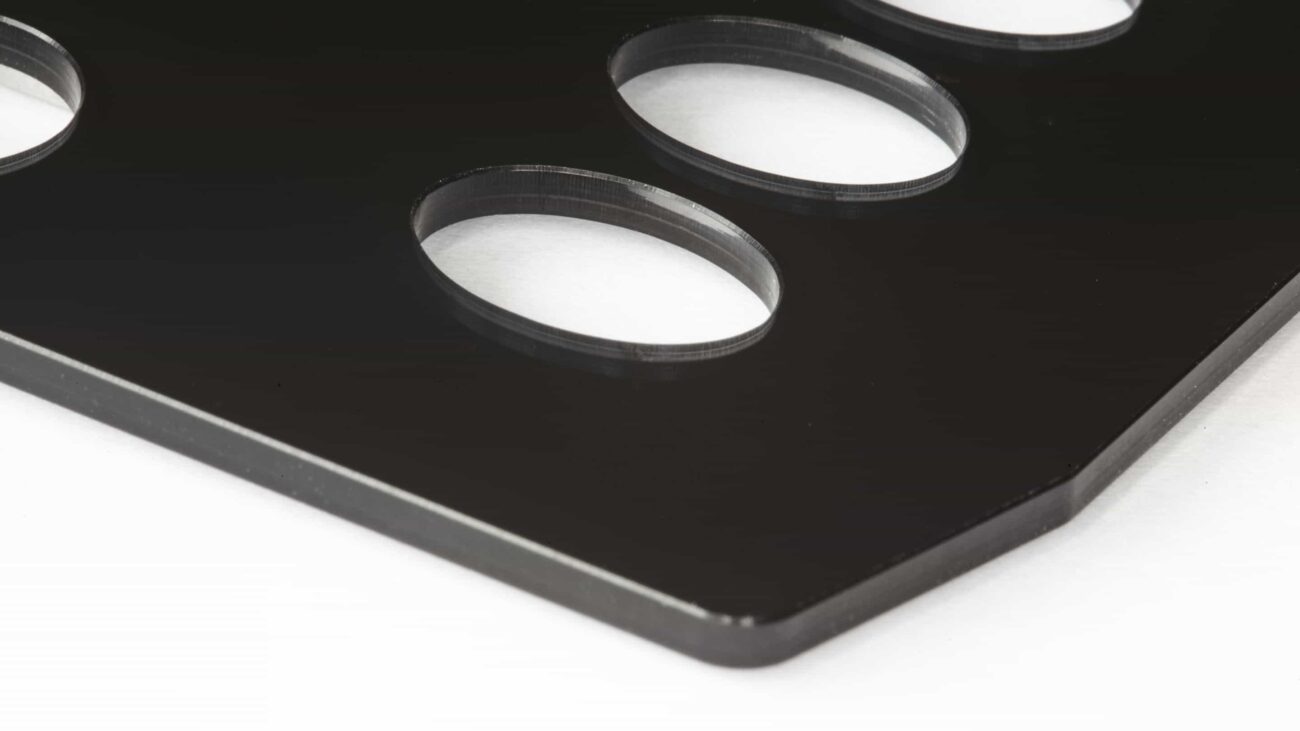
4. Holes, Cutouts and Openings: What Should Be Specified?
Holes and cutouts are common features in custom electronic cover glass.
However, different opening designs require different manufacturing considerations.
A complete engineering drawing should identify:
- Hole diameter and center coordinates.
- Distance between adjacent holes.
- Distance from holes to the external glass edge.
- Cutout width and height.
- Internal corner radius.
- Position relative to the main assembly datum.
Circular holes may be used for camera lenses, buttons or mounting components. Rectangular cutouts may accommodate connectors, switches or other mechanical features.
For openings with internal corners, sharp corners should not be assumed to be suitable for glass processing. Rounded internal corners can help reduce local stress concentration, but the appropriate radius must be reviewed according to the glass thickness and machining process.
There is also an important distinction between a physical opening and a transparent printed window.
A physical opening removes glass material. A transparent window in a black silk-screen border normally retains the glass but leaves a specified area unprinted.
These two requirements should be clearly distinguished in the drawing and artwork.
For additional manufacturing guidance, see Viracon’s glass notch and cutout guidelines.
5. Edge Finishing and Corner Radius
Edge finishing affects both the appearance and practical handling of custom glass panels.
Common edge requirements include:
Ground edges
Grinding removes sharp edges and helps prepare the component for further processing.
Polished edges
Polished edges provide a smoother and more refined appearance. They are often selected for visible electronic glass components.
Chamfered edges
A chamfer creates an angled transition along the edge. Its width and angle should be defined when the feature is required.
Rounded corners
Corner radii should be included in the drawing, particularly when the glass needs to fit a molded enclosure or a curved housing.
For glass used in touchscreen displays, edge quality should also be considered in relation to the assembly method. An unsuitable edge profile can interfere with the available adhesive area or mechanical support.
Do not assume that all edges receive the same finish. If different sides require different treatments, identify them individually on the drawing.
6. Black Silk-Screen Printing and Visible Areas
Black silk-screen printing is widely used on electronic cover glass to conceal internal components and create a clean product appearance.
However, decorative printing must be coordinated with the functional layout.
The drawing package should define:
- Printing side and viewing direction.
- Ink color and printing area.
- Border width.
- Transparent viewing windows.
- Camera and sensor openings.
- Alignment requirements between printing and glass geometry.
For example, a touchscreen panel may have a black printed border around the display area while leaving the central viewing window transparent.
If the border is too wide, it may overlap the active display area. If it is too narrow, internal components or adhesive zones may become visible.
For products involving multiple openings, the artwork should be checked against the mechanical drawing before production.
The glass manufacturer should receive the latest controlled artwork file, with clearly identified dimensions and reference points.
7. How Manufacturing Processes Affect Glass Design
Not every glass shape can be manufactured with the same level of difficulty.
The production route should be considered during the design stage.
CNC machining
CNC processing can produce defined external profiles, holes, slots and other custom geometries. However, minimum feature sizes and positioning capabilities depend on the equipment, glass thickness and part geometry.
Edge grinding and polishing
These processes determine the final edge condition and may influence finished dimensions.
Chemical or thermal strengthening
The strengthening process should be selected according to the glass material, thickness, geometry and application requirements.
Holes, cutouts and edge features need to be reviewed before strengthening because machining defects and unsuitable geometry can affect the final result.
Silk-screen printing
Printing introduces additional positional and registration requirements. Artwork should be reviewed together with the finished glass dimensions.
Optical bonding
If the glass will be bonded to an LCD or touchscreen module, the viewing area, adhesive coverage, alignment and overall stack-up should be considered during design.
Learn more about our custom glass manufacturing capabilities and the processing options available for OEM glass components.
8. What Engineers Should Check Before Approving a Drawing
Before releasing a custom cover glass drawing for production, engineers and purchasing teams should review the following items.
| Drawing item | What to confirm |
|---|---|
| Material | Glass type and material grade |
| Thickness | Nominal thickness and tolerance |
| External profile | Length, width and corner radius |
| Holes | Diameter, position and quantity |
| Cutouts | Dimensions and internal radii |
| Edge finish | Ground, polished or chamfered |
| Strengthening | Chemical or thermal treatment |
| Printing | Ink color, side and registration |
| Optical area | Clear window and active display area |
| Assembly | Adhesive, frame and mounting clearance |
| Inspection | Critical dimensions and acceptance criteria |
A drawing should also include a part number, revision number, units of measurement and clearly identified datum references.
For more demanding projects, a 2D engineering drawing should be supported by a 3D CAD model where appropriate.
The manufacturer should review the complete package and raise questions about unclear dimensions, conflicting requirements or difficult manufacturing features before releasing the part for production.
This review can save time during sample approval and reduce unnecessary modifications.
9. Working with a Custom Cover Glass Manufacturer
A capable supplier should do more than quote the dimensions shown on a drawing.
The manufacturer should understand how the glass will be assembled and identify processing details that could affect the finished component.
For example, a display cover glass with multiple sensor openings may require additional attention to machining sequence, edge quality, printing registration and dimensional inspection.
When discussing a new project, provide the following information:
- Application and end-product description.
- Glass material and nominal thickness, if already selected.
- Overall dimensions and engineering drawing.
- Hole, cutout and corner requirements.
- Surface treatment, such as AG, AR or AF.
- Printing artwork and transparent window requirements.
- Estimated prototype and production quantities.
If some specifications are not finalized, explain which items are still open for engineering review.
This allows the supplier to assess the project more accurately rather than making assumptions that may later affect the finished part.
Explore our custom cover glass solutions or contact Weiman to discuss your application and manufacturing requirements.
Conclusion
Successful custom cover glass design depends on the relationship between dimensions, tolerances, openings, edge finishing, printing and final assembly.
A drawing that clearly defines these requirements gives the manufacturer a better basis for evaluating feasibility, selecting suitable processing methods and preparing an accurate quotation.
For OEM buyers and product engineers, the best time to identify potential manufacturing problems is before the first sample is produced.
Need custom cover glass for an electronic display or touchscreen project? Share your engineering drawing and application requirements with Weiman for a manufacturing review.