 +86-13925515590
 kleinma@aliyun.com


Why Does Cover Glass Cracking During Assembly?

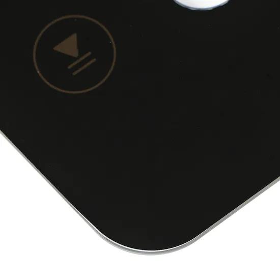
Information of Cover Glass Cracking
A cover glass panel can pass dimensional inspection and still crack after it is installed in an electronic device. In many cases, the problem is not simply the glass material or its thickness. The way the glass is machined, supported, bonded and fitted into the housing can also affect its mechanical performance.
This issue matters to manufacturers of industrial displays, touchscreen terminals, control panels, access control systems and other electronic equipment.
When a glass panel breaks during assembly, replacing it with a thicker or more expensive material is not always the right solution. The original cause may be a damaged edge, an undersized mounting clearance, excessive screw pressure or an uneven adhesive layer.
Understanding these factors before production can help OEM manufacturers reduce assembly failures and avoid repeated tooling and sampling costs.
1. Edge Damage During Machining or Handling
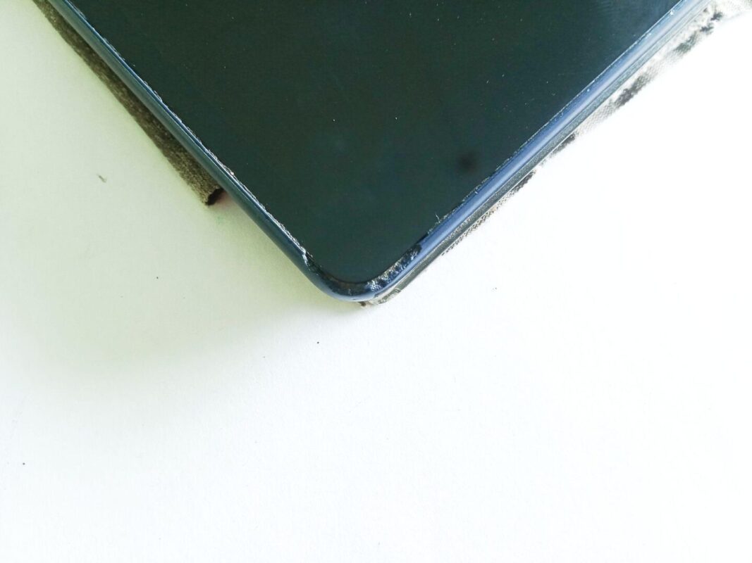
Glass is particularly sensitive to surface and edge defects when exposed to tensile stress. Small chips, scratches or cracks along the edge can become starting points for fracture.
These defects may occur during cutting, CNC grinding, drilling, transportation or manual handling.
For example, a glass panel may look acceptable from the front, while a small edge chip remains unnoticed near a mounting corner. When the panel is fitted into a tight housing, the local stress around that defect can increase.
To reduce this risk, manufacturers should review:
- Edge grinding and polishing requirements
- Corner radius and chamfer design
- Visible chips and edge defects
- Protection during transportation and handling
- Inspection criteria before assembly
The edge finish should be selected according to the glass geometry, thickness, strengthening process and installation method.
A drawing that only specifies the overall dimensions may not provide enough information to control edge quality.
2. Insufficient Clearance Between Glass and Housing
One common design issue is leaving too little space between the glass panel and its surrounding housing.
If the glass is tightly constrained by a metal or plastic frame, dimensional variation, housing deformation or temperature changes can create unwanted contact and localized loading.
This can be particularly problematic for electronic equipment with large glass panels or multiple fixing points.
During product design, engineers should consider:
- Glass dimensional tolerances
- Housing manufacturing tolerances
- Assembly alignment
- Thermal expansion of surrounding materials
- Required clearance around the glass perimeter
The actual clearance should be determined from the complete assembly design rather than using one universal value for every glass panel.
For OEM projects, reviewing the glass drawing together with the housing drawing is more useful than checking the glass dimensions in isolation.
3. Stress Concentration Around Holes and Cutouts
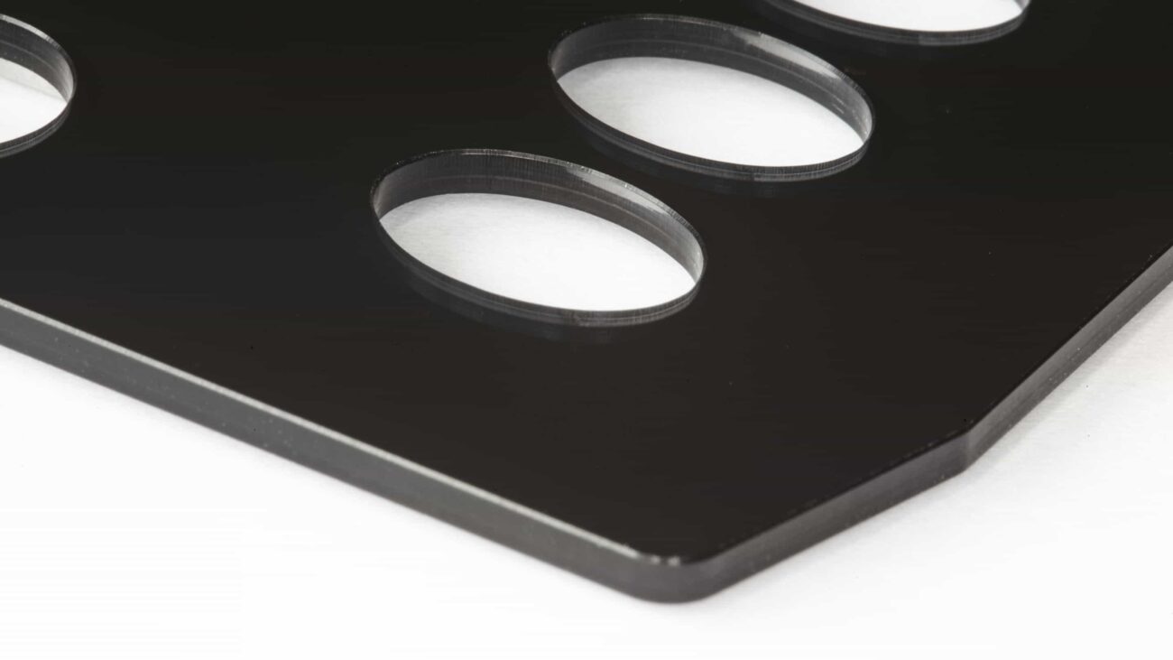
Mounting holes, notches and irregular openings can influence how mechanical loads are distributed through a glass panel.
A hole located close to an edge or corner may create a more demanding design condition, especially when the glass is exposed to fixing pressure or external impact.
Problems can also occur when the mounting screw, spacer or mechanical fitting contacts the glass directly.
Before production, engineers should review:
- Hole diameter and position
- Distance between holes and the glass edge
- Corner radius around openings
- Machining quality around drilled areas
- Clearance between screws and glass
- Whether the fixing system distributes pressure evenly
Holes and cutouts should be included in the original CAD drawing. Moving a hole after the first sample can affect the machining process and the surrounding structural design.
For complicated geometries, CNC machining requirements should be reviewed before the strengthening process.
4. Excessive Pressure From Screws and Mounting Clips
A glass panel should not be treated like a metal plate that can simply be tightened into position.
When mounting screws are over-tightened, or when clips apply uneven pressure, localized stress may develop around the fixing points.
This is especially important for thin electronic cover glass installed in compact devices.
Potential design problems include:
- Direct metal-to-glass contact
- Uneven pressure from mounting clips
- Incorrect spacer dimensions
- Misaligned screw holes
- Excessive tightening force
- Uneven support beneath the glass
The mounting structure should distribute loads appropriately and avoid hard contact between the glass and surrounding components.
Where necessary, suitable cushioning materials or compliant mounting interfaces can be considered as part of the assembly design.
The appropriate solution depends on the glass size, support arrangement, operating environment and housing material.
5. Uneven Adhesive Bonding and Bonding Stress
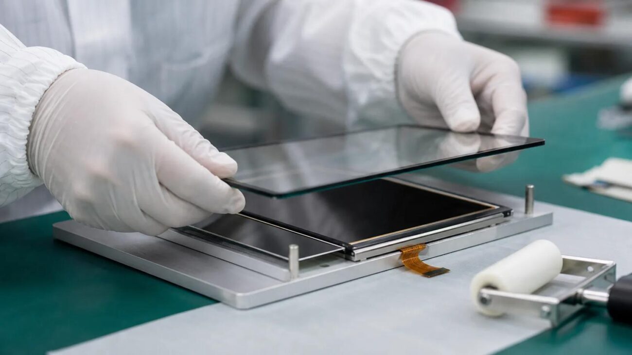
Adhesive bonding is widely used to install cover glass onto display modules, touch panels and electronic housings.
However, an uneven adhesive layer can introduce additional mechanical stress.
For example, if the bonding surface is not flat, the glass may be forced into a different position during assembly. Uneven adhesive thickness, excessive compression or incompatible bonding materials may also affect the finished assembly.
For projects involving double-sided adhesive tape, VHB tape or OCA optical bonding, engineers should consider:
- Adhesive thickness and compression
- Bonding surface flatness
- Adhesive coverage and positioning
- Compatibility with the glass printing area
- Assembly pressure and curing conditions
- Temperature changes during product operation
OCA optical bonding and structural adhesive bonding are not interchangeable processes. Their selection depends on the display structure and the required optical and mechanical performance.
A bonding specification should therefore be confirmed before mass production rather than decided only after the glass sample is completed.
6. Temperature Changes and Thermal Stress
Glass and its surrounding materials may expand at different rates when temperature changes.
If a glass panel is tightly constrained inside a housing, temperature variations can contribute to mechanical stress.
Uneven heating can also create temperature differences between different areas of the glass.
This issue deserves attention in equipment installed outdoors, near heat-generating electronic components or in environments with significant temperature fluctuations.
Design reviews should consider:
- Operating and storage temperature ranges
- Temperature differences across the glass surface
- Housing material and thermal expansion
- Mounting clearance
- Adhesive performance under temperature cycling
- Whether the glass is exposed to direct sunlight or localized heating
Thermal stress should not be confused with impact damage or manufacturing defects. The fracture pattern and the assembly conditions need to be examined together.
How OEM Manufacturers Can Reduce Cover Glass Assembly Failures
When developing a new electronic product, it is better to review the glass and housing as one assembly rather than treating them as two separate components.
The following checks can help identify potential problems before mass production.
| Design area | What to review |
|---|---|
| Glass edges | Grinding, polishing, corner radius and edge defects |
| Dimensions | Overall tolerances and housing clearance |
| Holes | Diameter, position and edge distance |
| Mounting | Screw pressure, clips and support points |
| Bonding | Adhesive thickness, coverage and flatness |
| Environment | Operating temperature and thermal expansion |
For new OEM projects, a practical process is to review the drawing, manufacture a prototype, inspect the finished glass, assemble it into the housing and evaluate the complete device.
If cracking occurs, preserve the broken pieces where possible and record the fracture origin, assembly sequence and mounting conditions. This information is more useful for failure analysis than simply requesting a replacement glass panel.
Custom Cover Glass Manufacturing for Reliable Assembly
At WM Cover Glass, custom glass components can be manufactured according to customer drawings, samples and technical requirements.
Available processing options include:
- CNC cutting, drilling and precision shaping
- Custom edge grinding and polishing
- Chemical strengthening and thermal tempering
- Black and customized silk-screen printing
- AR, AG and AF surface treatments
- Adhesive bonding and OCA lamination
- Dimensional and appearance inspection
For projects with mounting holes, irregular outlines or adhesive bonding requirements, we recommend confirming the glass drawing and assembly structure before sample production.
A complete technical drawing should include the glass dimensions, thickness, hole positions, edge requirements, printing areas and relevant bonding details.
Discuss Your Custom Cover Glass Project
Are you developing a touchscreen, industrial control panel, access control terminal or other electronic device that requires a custom glass front panel?
Send WM Cover Glass your 2D drawing, sample or assembly specifications. We can review the glass processing requirements and discuss suitable manufacturing options for your project.
Contact WM Cover Glass to discuss your custom cover glass requirements.