 +86-13925515590
 kleinma@aliyun.com


Custom Glass Technical Drawing

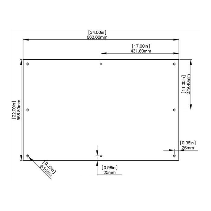
Custom Glass Technical Drawing: How to Prepare CAD and DXF Files for Manufacturing
A technical drawing is one of the most important documents when developing custom cover glass.
For OEM manufacturers, an incomplete or unclear drawing can create problems during quotation, CNC programming, production setup and final inspection.
Providing a suitable CAD file together with clear manufacturing specifications helps reduce misunderstandings between the product designer and glass manufacturer.
This guide explains how to prepare a custom glass technical drawing for OEM production.
1. Why a Technical Drawing Is Important
Custom cover glass is often manufactured with specific dimensions, holes, cutouts, corner radii, edge profiles and printed areas.
A product photograph or simple overall measurement cannot communicate all these details.
A technical drawing provides the dimensional information needed to evaluate:
- Glass blank dimensions
- Overall shape
- Thickness
- Corner geometry
- Hole positions
- CNC openings
- Edge finishing
- Printing areas
- Assembly interfaces
The drawing also provides a reference for inspection after production.
2. Choose the Appropriate Drawing File Format
OEM buyers may provide different file formats depending on their design software.
DXF Files
DXF files are commonly used for two-dimensional geometry and CNC-related design information.
They can provide outlines, holes, slots and other machining features.
For reliable processing, the drawing should use clear geometry without duplicate lines, open contours or unnecessary construction objects.
DWG Files
DWG is commonly used for CAD drawings containing dimensions, layers and design information.
It can be useful when the manufacturing supplier needs to review both geometry and drawing annotations.
PDF Drawings
PDF drawings are convenient for reviewing dimensions, notes, tolerances and revision information.
However, a PDF alone may not provide editable geometry for CNC programming.
STEP Files
STEP files are useful when the glass component includes three-dimensional geometry or complex spatial relationships.
For many flat cover glass components, a 2D drawing may be sufficient, but 3D files can help clarify complicated designs.
3. Include Complete Overall Dimensions
The drawing should clearly define the basic dimensions of the glass panel.
These may include:
- Overall length
- Overall width
- Glass thickness
- Corner radius
- External contour
- Angular dimensions
- Special curved sections
Avoid relying on scaled measurements from a drawing image.
Every critical dimension should be explicitly identified.
4. Define Holes, Slots and Cutouts
CNC machining requirements must be communicated clearly.
For each opening, provide:
- Hole diameter
- Hole center coordinates
- Distance from reference edges
- Slot length and width
- Cutout dimensions
- Corner radius
- Position tolerance
For irregular shapes, a detailed CAD outline is particularly helpful.
If a hole is close to the glass edge, the surrounding geometry and required edge condition should also be reviewed for manufacturing feasibility.
5. Establish Clear Datums and Reference Points
A datum is a reference used to define and evaluate the position or orientation of a feature.
For custom cover glass, suitable reference features may include two external edges, a defined center point or selected mounting holes.
The drawing should make it clear how the position of each critical feature is measured.
For example, defining a hole position from two reference edges is generally more useful than providing an unclear dimension from an arbitrary location.
This becomes particularly important when several holes, printed windows and external contours must align with an electronic module.
6. Specify Edge Finishing and Surface Requirements
The drawing should identify the required edge treatment.
Possible options include:
- Ground edges
- Polished edges
- Chamfered edges
- Beveled edges
- Custom edge profiles
Also specify any surface requirements, such as:
- Clear glass
- AG treatment
- AR coating
- AF coating
- Black border printing
- Logo printing
Where these requirements are not shown in the main drawing, a separate specification sheet can be provided.
Explore our glass edge processing capabilities and AR, AG and AF coating options.
7. Control Drawing Revisions
Drawing revision control is essential when a product moves from prototype to mass production.
An updated hole position, border width or external dimension can affect tooling, programming and assembly.
Each drawing should include:
- Part number
- Drawing title
- Revision number
- Issue date
- Material specification
- Thickness
- Units
- Approval status
When a revision is released, outdated files should be clearly identified to prevent accidental use during manufacturing.
The approved drawing should be linked to the corresponding production order and inspection records.
8. A Practical Checklist Before Sending Your Drawing
Before requesting a custom cover glass quotation, check that your technical package includes:
- A complete 2D drawing.
- An editable DXF or CAD file where applicable.
- Overall dimensions and thickness.
- Hole and cutout coordinates.
- Corner radius and edge specifications.
- Material requirements.
- Surface treatment requirements.
- Printing artwork where applicable.
- Critical dimensional tolerances.
- Drawing revision and estimated quantity.
If some specifications are not yet finalized, provide the current drawing and identify the open design questions.
This allows the manufacturer to review the design and identify information that needs confirmation.
Frequently Asked Questions
Is a PDF enough for custom glass manufacturing?
A PDF can communicate dimensions and specifications, but an editable DXF, DWG or suitable CAD file is helpful when precise geometry is required for CNC processing.
Do I need to provide a 3D STEP file?
Not always. A complete 2D drawing is often sufficient for flat cover glass. STEP files can be useful for complex shapes or assembly reviews.
Should hole positions be measured from the glass edge?
The drawing should define a consistent datum or reference system. Hole coordinates should not be left open to interpretation.
Can a manufacturer review an incomplete drawing?
Yes. An initial drawing or sample can be used for preliminary feasibility review, although missing critical dimensions may prevent a firm quotation.
Send Your Glass Drawing for OEM Review
Have a DXF, DWG, PDF or STEP file for a custom cover glass project?
Send us your drawing, material preference, thickness, processing requirements and expected quantity.
WM Cover Glass can review your drawing for glass cutting, CNC machining, edge processing, strengthening and printing requirements.