 +86-13925515590
 kleinma@aliyun.com


Custom Cover Glass Tolerances: Dimensions, Thickness and Hole Position Requirements

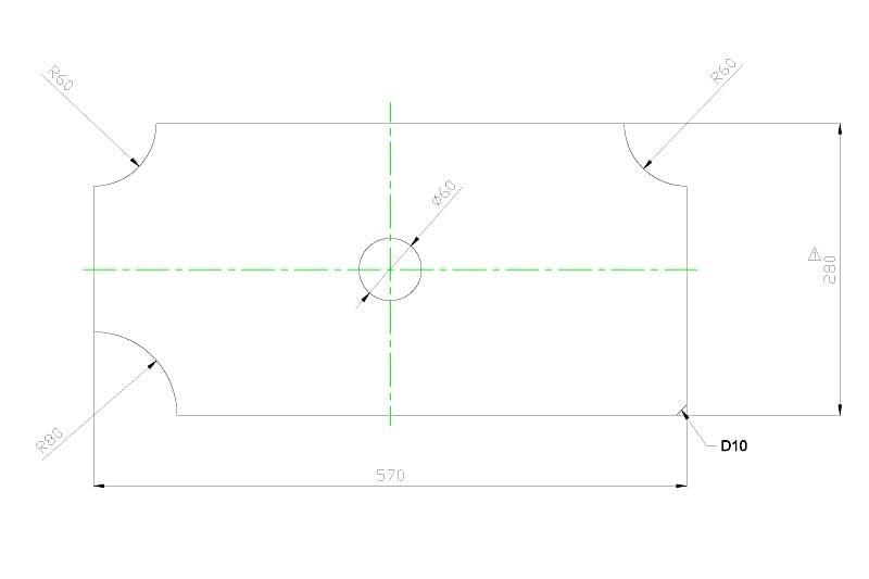
Custom Cover Glass Tolerances: Dimensions, Thickness and Hole Position Requirements
When developing a custom cover glass component, dimensional accuracy is just as important as material selection and optical performance. A glass panel may meet its nominal length and width requirements but still fail during assembly because a mounting hole is misplaced, an edge clearance is insufficient or the thickness variation affects the bonding gap.
For OEM manufacturers, specifying glass tolerances requires more than adding a general ± value to every dimension. Different features serve different functions, and each should be evaluated according to its manufacturing process and assembly requirements.
This guide explains how to define dimensional tolerances for custom cover glass, including overall dimensions, thickness, drilled holes, cutouts, edge distances and geometric requirements. It also covers drawing preparation and inspection considerations to help engineering and purchasing teams reduce avoidable production problems.
1. Why Dimensional Tolerances Matter in Custom Cover Glass
Custom cover glass is often installed into a plastic or metal housing, bonded to a display module or positioned over an optical component. Its dimensions directly affect the fit and function of the finished assembly.
Several types of dimensional variation can create problems:
- A glass panel that is too large may interfere with the housing or installation frame.
- A panel that is too small may leave an uneven perimeter gap.
- Incorrect hole positions can prevent mounting screws or locating pins from fitting.
- Thickness variation can affect adhesive thickness and assembly height.
- Poorly defined corner radii can cause interference with the enclosure.
- Excessive edge damage may create cosmetic or mechanical concerns.
The important point is that not every dimension has the same functional importance. An external length may allow some variation, while a sensor opening or mounting-hole position may require much tighter control.
A practical tolerance specification should therefore be based on assembly function, not simply on the smallest tolerance that can be written on a drawing.
For general dimensional tolerances on engineering drawings, designers may refer to ISO 2768-1 as a reference for general tolerance principles. However, this standard is not specifically developed for precision cover glass manufacturing. Critical glass dimensions should always be assigned individual tolerances based on the part geometry and manufacturing process.
2. Overall Length, Width and External Profile Tolerances
Length and width are usually the first dimensions specified for a rectangular cover glass panel.
However, custom glass components can also include rounded corners, angled edges, irregular profiles and internal cutouts. These features may require separate dimensional controls.
For a typical rectangular cover glass, the drawing should identify:
- Overall length and width
- Corner radius
- External profile shape
- Edge-to-edge dimensions
- Reference datum or measurement locations
- Dimensional tolerance for each critical feature
For irregular shapes, it is useful to provide a dimensioned drawing or CAD file instead of relying only on an overall length and width.
Why General Tolerances May Not Be Enough
A general tolerance can simplify engineering drawings, but it should not automatically be applied to every glass feature.
For example, a general tolerance intended for machined metal parts may not accurately represent the capabilities of a glass cutting, grinding or CNC process.
ISO 2768-1 provides general tolerances for linear and angular dimensions without individual tolerance indications. However, its scope is primarily related to parts produced by metal removal or formed from sheet metal. It should not be treated as a universal glass fabrication tolerance standard.
For custom cover glass, identify critical dimensions individually and confirm the proposed tolerances with the glass manufacturer.
3. Cover Glass Thickness Tolerance and Assembly Requirements
Glass thickness affects more than the overall component height. It can influence optical performance, bonding design, mechanical properties and the fit between the glass and its supporting structure.
For example, a touchscreen cover lens bonded to an LCD module may require a controlled bonding gap. Thickness variation can change the amount of adhesive needed and affect the final assembly height.
When specifying cover glass thickness, include:
- Nominal glass thickness
- Upper and lower thickness limits
- Measurement method
- Measurement locations
- Whether the requirement applies before or after strengthening
- Whether coatings or printing are included in the finished thickness requirement
A useful drawing callout should state both the nominal value and the permitted variation.
For example:
Nominal thickness: 1.10 mm ± 0.05 mm
This is an illustrative specification only, not a universal manufacturing capability or recommended tolerance for every application. The appropriate range depends on the glass material, thickness, processing route and supplier capability.
Thickness Variation Across the Panel
For larger or optically sensitive components, a single thickness measurement may not fully describe the part.
Engineering teams may also need to consider thickness variation across multiple measurement locations, particularly when the glass is used in precision assemblies.
If this is important to the product, specify whether the requirement refers to:
- Maximum and minimum measured thickness
- Total thickness variation across the component
- Thickness at designated inspection points
- Finished component thickness after surface treatment
Avoid using these terms interchangeably. A supplier should know exactly which characteristic must be measured and reported.
4. Glass Hole Position Tolerance and CNC Drilling Requirements
Hole position is one of the most important dimensions for custom cover glass with mounting features, sensor openings or camera windows.
A hole may have the correct diameter but still fail to fit if its center is incorrectly positioned.
For this reason, a complete glass drilling specification should include:
Hole diameter: Defines the size of the opening.
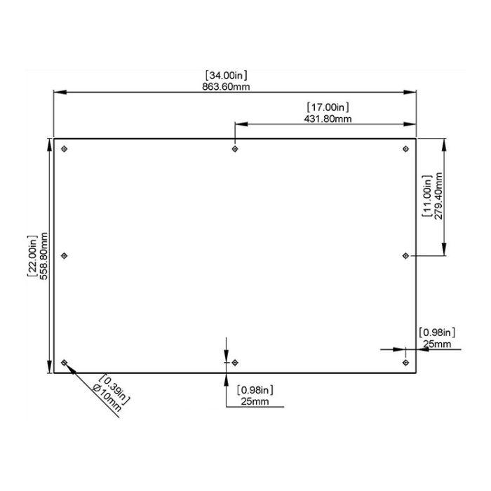
Hole center coordinates: Defines the location of the hole relative to the drawing datums.
Hole-to-edge distance: Defines the minimum distance between the hole and the external glass edge.
Hole-to-hole spacing: Controls the distance between multiple holes.
Hole geometry: Identifies whether the hole is straight, countersunk, stepped or has another special profile.
Define Hole Positions from Clear Datums
Avoid describing a hole position only as a distance from an unspecified edge.
Instead, establish a clear coordinate reference.
For example:
- Datum A: lower reference edge
- Datum B: left reference edge
- Hole center: X = 25.00 mm from Datum B
- Hole center: Y = 18.00 mm from Datum A
- Hole diameter: Ø3.00 mm
The permitted positional variation should be defined separately according to the required fit and measurement method.
For multiple holes, consider specifying the center-to-center spacing or a positional tolerance relative to a shared datum reference.
This helps prevent accumulated measurement errors when different holes are measured independently.
Hole-to-Edge Distance
The distance between a drilled hole and the nearest glass edge is important for both machining feasibility and finished-part reliability.
Insufficient edge distance can increase the risk of edge damage, cracking or breakage during processing, handling and assembly.
The suitable distance depends on several factors:
- Glass material and thickness
- Hole diameter
- Hole shape and edge profile
- Machining equipment and process
- Distance between adjacent holes
- Subsequent strengthening and assembly conditions
There is no single hole-to-edge ratio that should be applied to every glass design. The geometry should be reviewed before tooling or sample production.
5. Cutouts, Notches and Internal Opening Tolerances
Custom cover glass frequently includes more than round holes.
Examples include:
- Rectangular display windows
- Camera and sensor openings
- Speaker openings
- Connector access slots
- Side notches
- Irregular internal cutouts
These features should be dimensioned individually because their positions and shapes often determine whether the glass fits the enclosure.
For rectangular cutouts, specify width, height, corner radius and location.
For slots, include overall length, width, end radius and orientation.
For irregular cutouts, a controlled CAD profile can be more useful than a long list of disconnected dimensions.
If the cutout is used for an optical sensor or camera, also define the required clear aperture and the location of any printed masking area.
A glass opening may be dimensionally correct while the final usable optical window is still too small because of the surrounding black border or adhesive structure.
6. Edge Processing, Chamfers and Corner Radius
Edge finishing should be included in the engineering drawing rather than left as an informal production instruction.
Common edge requirements include:
- Ground edges
- Polished edges
- Chamfered edges
- Rounded corners
- Custom edge profiles
For a chamfered edge, specify the chamfer width and angle where relevant.
For rounded corners, provide the radius and identify whether all corners share the same value.
For polished edges, define the appearance and inspection requirements separately from dimensional accuracy.
This distinction matters because a glass component can meet its external dimensions while still having unacceptable edge chips or polishing marks.
If the edge is visible after installation, cosmetic acceptance criteria should be agreed upon before mass production.
7. How Glass Processing Sequence Affects Dimensional Accuracy
The manufacturing sequence should be considered when defining glass tolerances.
A typical custom cover glass process may include cutting, CNC machining, edge grinding, polishing, strengthening, printing and coating. The actual sequence depends on the material and product design.
For example, drilling and edge machining are generally planned before chemical strengthening or thermal tempering. Post-strengthening machining is normally restricted and must not be assumed to be available.
Other considerations include:
CNC machining: Hole diameter, position and profile accuracy depend on the machine setup, tooling and material condition.
Edge grinding: Material removal changes the final external dimensions, so finishing allowances should be considered.
Chemical strengthening: The process introduces surface compressive stress but does not eliminate the need to control the dimensions established during earlier machining.
Silk-screen printing: Printed borders and openings need their own alignment requirements. The glass dimensions and printed pattern dimensions are separate characteristics.
Coating: Surface treatments may affect the final surface stack and should be considered where the finished assembly has strict height or optical requirements.
For these reasons, the drawing should identify whether dimensions apply to the machined substrate or the finished component.
8. How to Inspect Custom Cover Glass Dimensions
A tolerance is only useful when the measurement method is understood by both the buyer and the manufacturer.
Different features may require different inspection equipment.
| Feature | Possible inspection method |
|---|---|
| Overall length and width | Caliper or optical measuring system |
| Glass thickness | Micrometer or suitable thickness gauge |
| Hole diameter | Pin gauge or optical measurement |
| Hole center position | Vision measuring system or CMM |
| Corner radius | Optical comparator or image measurement |
| Cutout profile | Optical measurement or calibrated vision system |
| Edge condition | Visual inspection under agreed conditions |
| Flatness | Suitable surface measurement setup |
The inspection method should be appropriate for the tolerance being evaluated. A standard handheld caliper may not provide sufficient measurement confidence for a very tight hole-position requirement.
For production acceptance, consider agreeing on:
- Inspection equipment and calibration
- Measurement reference points
- Sampling frequency
- First-article inspection requirements
- Dimensional inspection report format
- Acceptable edge and surface defects
For quality planning, also distinguish between first-article verification and ongoing production inspection.
9. Example: Preparing a Cover Glass Drawing for OEM Quotation
Consider a hypothetical rectangular touchscreen cover glass with two mounting holes and one internal sensor opening.
A preliminary drawing specification might include:
| Feature | Example specification |
|---|---|
| External size | 120.00 × 75.00 mm |
| Glass thickness | 1.10 mm ± 0.05 mm |
| Mounting holes | 2 × Ø3.00 mm |
| Hole center X positions | 15.00 mm and 105.00 mm |
| Hole center Y position | 8.00 mm |
| Sensor opening | 8.00 × 5.00 mm |
| Corner radius | R5.00 mm |
| Edge finish | Ground and polished |
| Surface treatment | Chemical strengthening and optional AF coating |
| Printing | Black border with defined optical opening |
These values are examples for explaining drawing structure. They are not guaranteed process tolerances or a recommended design for every product.
Before quotation, the buyer should add the actual permitted tolerances for each critical dimension, identify the datums and confirm the required edge and surface quality.
The supplier can then review the geometry, material, thickness and manufacturing sequence to evaluate feasibility.
10. What to Include in a Custom Cover Glass RFQ
A complete RFQ should provide enough information for a manufacturer to evaluate both the part design and the manufacturing process.
Before sending your inquiry, prepare:
- A dimensioned 2D engineering drawing.
- A DXF, DWG or STEP file where applicable.
- Glass material and nominal thickness.
- Overall dimensions and critical tolerances.
- Hole diameters, center coordinates and edge distances.
- Cutout dimensions and corner radii.
- Edge grinding or polishing requirements.
- Chemical strengthening specifications, if required.
- AR, AG or AF coating requirements, if applicable.
- Silk-screen printing and masking details.
- Prototype quantity and estimated production volume.
- Inspection and packaging requirements.
For drawings with particularly tight tolerances, identify which dimensions are critical to function and which are reference dimensions.
This allows the manufacturer to focus engineering review on the features that matter most to assembly and product performance.
Conclusion: Define Tolerances Around the Finished Assembly
Custom cover glass tolerances should be based on the actual design and assembly requirements rather than a single general tolerance applied to the entire drawing.
Overall dimensions, thickness, hole positions, edge distances, cutouts and corner profiles each require appropriate controls. Their feasibility depends on material, thickness, machining sequence and inspection method.
For OEM projects, the most effective approach is to provide a clear drawing, identify functional datums, specify critical dimensions individually and review manufacturing feasibility before sample production.
Need custom cover glass manufactured to your engineering drawing?
Send us your 2D drawing, CAD files, glass material, thickness, critical tolerances and estimated order quantity. Our team can review the design and evaluate suitable glass cutting, CNC machining, edge processing, strengthening and surface treatment options.
Contact us for a custom cover glass quotation.
Frequently Asked Questions
What is a typical tolerance for custom cover glass?
There is no universal tolerance for all custom cover glass. Achievable values depend on glass thickness, material, external geometry, machining method and inspection requirements. Critical dimensions should be reviewed with the manufacturer before finalizing the drawing.
How should hole position be specified on a glass drawing?
Define the hole center coordinates from clear datum edges or a datum reference system. Include the hole diameter, positional tolerance and relevant edge-distance requirements.
Does glass thickness tolerance affect assembly?
Yes. Thickness variation can affect adhesive gaps, mounting height, enclosure fit and the relationship between the cover glass and display module.
Can holes be drilled after glass strengthening?
In general, drilling and precision edge machining should be completed before chemical strengthening or thermal tempering. Machining after strengthening should not be assumed to be feasible because it can compromise the glass.
Should all dimensions use the same tolerance?
No. External dimensions, hole positions, cutouts, thickness and cosmetic features have different functional requirements. Critical features should receive individual tolerance callouts.
What files should I send for a custom glass quotation?
A dimensioned PDF drawing is a useful starting point. DXF, DWG or STEP files can provide additional geometry information. Include material, thickness, surface treatments, quantities and critical dimensional requirements.