 +86-13925515590
 kleinma@aliyun.com

What to Include in a Printed Glass Control Panel Drawing

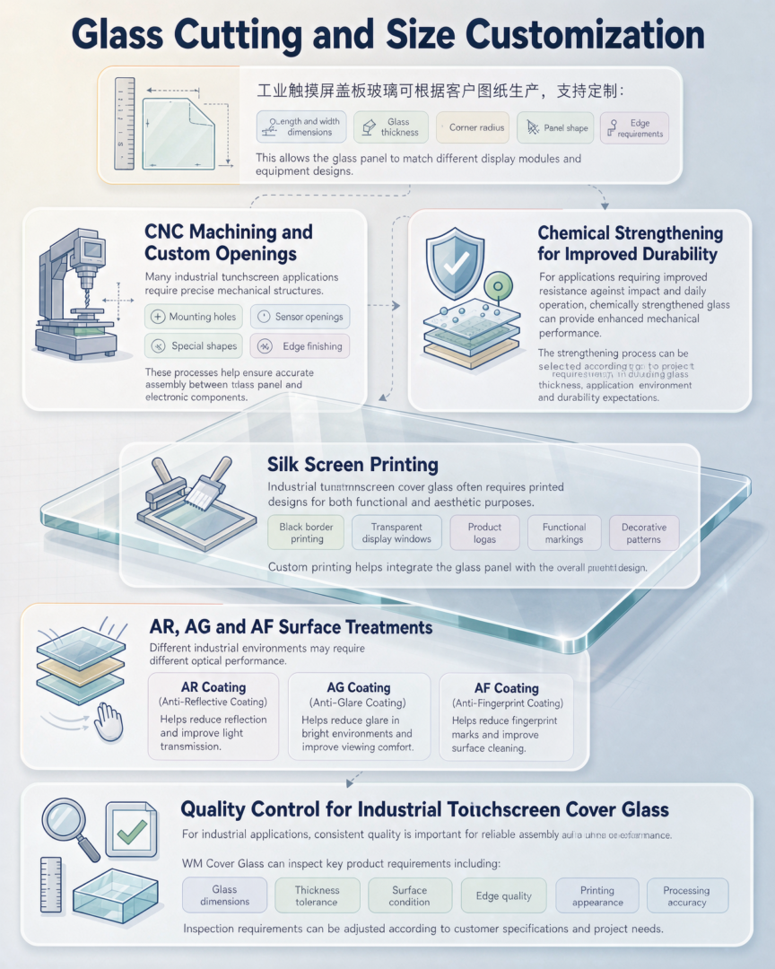
A printed glass control panel drawing should show more than the outside dimensions of the glass. When the panel is used as a visible control surface, the drawing normally needs to define the glass thickness, hole locations, corner geometry, printed areas, display windows and other features that affect assembly.
For a supplier, a clear drawing makes it easier to evaluate printed glass control panel manufacturing, CNC machining, screen printing and glass strengthening requirements before quoting.
This guide covers the details worth including when preparing a drawing for a custom printed glass control panel.
1. Overall Glass Panel Dimensions
Start with the finished dimensions of the glass.
The drawing should identify:
- Overall length
- Overall width
- Glass thickness
- Corner radius
- Finished panel shape
- Dimensional tolerances
For a rectangular panel, the length and width may be straightforward. However, an irregular custom glass control panel should include enough reference dimensions to define the complete profile.
If the glass fits into a metal or plastic enclosure, the drawing should also identify the dimensions that control the actual fit.
For more information about custom panel dimensions and glass processing, see our Glass Cutting capability.
2. Glass Thickness and Material
Glass thickness should be specified rather than left to the supplier to select.
Common project specifications may include the required thickness, glass type and strengthening method. Depending on the application, the panel may use soda-lime glass, chemically strengthened glass or aluminosilicate glass.
Thickness affects the mechanical design, weight, edge processing and compatibility with the enclosure.
If the glass will be installed close to a display or touch sensor, the thickness should also be checked against the assembly design.
3. Hole Diameter and Hole Position
Mounting holes are one of the most important details on a glass control panel drawing.
A drawing should show:
- Hole diameter
- Hole center position
- Distance between holes
- Distance from hole center to glass edge
- Required hole tolerance
- Hole quantity
- Special hole geometry if applicable
For example, a four-hole mounting pattern should not simply be marked “4 holes.” The drawing should provide the hole locations or the relevant center-to-center dimensions.
This information is especially important for a glass panel with mounting holes because the holes need to align with screws, inserts, brackets or spacers during assembly.
See our CNC Machining for Cover Glass page for more information about machined glass features.
4. Corner Radius and Edge Geometry
The outside corners of a printed glass panel should have a defined radius when they need to match an enclosure or frame.
The drawing may also specify:
- Edge chamfer
- Edge polish
- Flat edge
- Edge treatment
- Edge tolerance
A small difference in corner radius can affect how the glass sits inside a molded plastic frame.
For assemblies where the glass is mechanically retained, the edge condition should therefore be treated as part of the mechanical specification rather than an appearance detail.
5. Printed Border Dimensions
The printed border is often one of the most visible parts of a screen printed glass panel.
The drawing should indicate the width and position of the printed border relative to the finished glass edge.
If the border covers an adhesive area or internal components, the opaque region should be clearly identified.
Useful information includes:
- Border width
- Border-to-edge distance
- Printing side
- Opaque area
- Transparent window
- Color
- Printing tolerance
For black borders around a display, it is useful to provide the active display opening as a separate dimension instead of relying only on the overall glass dimensions.
6. Artwork, Symbols and Text
The mechanical drawing defines where the graphics belong, while the artwork file defines what is actually printed.
For a printed glass control panel, the artwork may contain:
- Button symbols
- Operating labels
- Logos
- Numbers
- Scale markings
- Indicator symbols
- Warning icons
- Function names
Artwork should preferably be supplied as a vector file when possible.
The drawing should identify the artwork revision so that the supplier can distinguish between different versions during production.
If text or symbols need to align with CNC holes or other openings, these features should use common reference dimensions.
7. Transparent Display and Indicator Areas
Many control panels combine printed graphics with transparent areas.
For example, a panel may contain a black printed border with a clear window over an LCD, LED indicator or touchscreen.
The drawing should identify:
Printed area → transparent window → display opening → component position
This is particularly useful when the glass is installed over an electronic display.
If the transparent window has a specific optical requirement, include that requirement separately rather than assuming standard clear glass will be suitable.
8. Printing Color and Printing Method
The drawing should identify the required printing color and, where necessary, the color reference.
For example:
- Black
- White
- Gray
- Custom color
- Multi-color printing
The printing specification should also state whether the graphic is intended to be viewed through the glass or from the opposite side.
This matters because the printing sequence and viewing orientation can affect the final appearance.
For custom glass control panel printing, see our Silk Screen Printing capability.
9. Printing Alignment with Holes and Cut-Outs
When a panel contains both printed graphics and CNC-machined openings, their relationship should be clear on the drawing.
A common example is:
printed button symbol → corresponding hole → switch underneath
Another is:
black printed border → display opening → LCD active area
The drawing should use common datum references where possible. This makes it easier to evaluate the relative position of the graphics and machined features.
This detail becomes increasingly important when the panel contains multiple buttons, indicators or irregular openings.
10. Surface Treatment
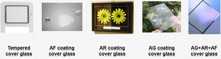
The drawing should identify whether the glass requires a surface treatment.
Depending on the application, specifications may include:
- Anti-glare (AG)
- Anti-reflective (AR)
- Anti-fingerprint (AF)
- Etched or matte surface
- Other project-specific coatings
For a control interface used under strong factory lighting, an anti-glare glass control panel may be considered to reduce distracting reflections.
For a display-based interface, an AR treatment may be more appropriate when reflected light needs to be controlled without changing the intended appearance of the display.
See our AR / AG / AF Coatings page for related processing information.
11. Chemical Strengthening Requirements
If the panel requires improved mechanical performance, the drawing or specification should identify the required strengthening process.
For example, the project may specify:
- Chemical strengthening
- Thermal tempering
- Required glass type
- Required thickness
- Project-specific testing requirements
Chemical strengthening can be considered for thin glass panels used in equipment where the surface is exposed to repeated handling.
The suitability of a strengthening process depends on the glass composition and thickness, so these requirements should be reviewed before production.
More information is available on our Chemical Strengthening & Thermal Tempering page.
12. Surface and Appearance Requirements
A printed glass panel drawing should define appearance requirements when surface quality is important.
Possible requirements include:
- Surface scratches
- Chips
- Edge defects
- Bubbles
- Printing defects
- Color variation
- Contamination
- Pinholes in printed areas
It is better to define acceptance criteria before production than to discuss defects after the panels have been delivered.
Our Quality Inspection page provides additional information about dimensional and appearance inspection.
For general engineering drawing and tolerancing practices, ASME Y14.5 is a useful reference for buyers preparing dimensional drawings.
13. Drawing Revision and Part Number
A surprisingly common source of production mistakes is an outdated drawing.
Every production drawing should ideally contain:
- Part number
- Drawing number
- Revision
- Date
- Material
- Thickness
- Quantity
- Approval information
If the printing artwork has a separate revision, identify it as well.
For repeat orders, the glass drawing and artwork revision should be checked together before production.
14. Packaging and Handling Requirements
Packaging requirements do not always need to appear on the mechanical drawing, but they should be communicated before production for fragile glass components.
For example, buyers may specify:
- Individual separators
- Protective film
- Quantity per box
- Edge protection
- Export packaging
- Label requirements
This becomes particularly relevant for larger panels, thin glass or panels with machined holes and cut-outs.
A Practical Drawing Checklist
Before sending a printed glass control panel drawing to a supplier, check that the following information is available:
| Requirement | Included? |
|---|---|
| Overall glass dimensions | □ |
| Glass thickness | □ |
| Glass material | □ |
| Corner radius | □ |
| Edge processing | □ |
| Hole diameter | □ |
| Hole positions | □ |
| Cut-outs and slots | □ |
| Printed border dimensions | □ |
| Printing artwork | □ |
| Printing colors | □ |
| Transparent areas | □ |
| Surface treatment | □ |
| Strengthening requirement | □ |
| Dimensional tolerances | □ |
| Appearance requirements | □ |
| Part number | □ |
| Drawing revision | □ |
| Required quantity | □ |
A drawing containing these details gives the supplier a much better basis for reviewing the project and preparing a quotation.
When a PDF Drawing Is Enough
For an initial RFQ, a PDF drawing is often sufficient if all critical dimensions and specifications are visible.
A supplier may request a CAD file later when the design contains complex profiles, multiple holes, irregular cut-outs or tight relationships between machined features.
If the artwork is separate from the mechanical drawing, send both files together and make sure the revision numbers correspond.
Request a Quote for a Printed Glass Control Panel
If you already have a glass drawing, you do not need to prepare a long product description before contacting a supplier.
Send the drawing, artwork, required quantity and any special requirements such as chemical strengthening, CNC machining, AG/AR/AF treatment or adhesive bonding.
You can also review our Printed Glass Control Panel product page for the available processing options.
A clear drawing gives both sides the same reference before pricing and production begin. It also makes it easier to identify dimensional, printing and assembly requirements at the quotation stage rather than after the glass has been manufactured.